New Austrian Tunneling Method (NATM) : Emphasis on Execution Cycle Methodology

Abstract: Tunneling is a vast and continuously growing field in the construction industry. It is considered as the most complex construction methods considering the unexpected behavior of the rock mass during the construction phase. Generally, wedge formations, shear zones, debris material, presence of nalas/small water channels, less overburden, heavy ingress of water and many more are the conditions which may be encountered during the execution phase. Therefore, a precise and safe method is required which could save time and provides safer environment for the construction. New Austrian Tunneling Method (NATM) of tunneling is considered as the most effective method in the region of varying geology, as it works on the observational approach of tunneling.

Keywords: NATM; Himalayan Geology; Tunneling Method

A. NATM CONCEPT

The New Austrian Tunneling Method can be defined as a support method to stabilize the tunnel perimeter with the help of sprayed concrete, anchors and other support and uses regular monitoring to control stability of the tunnel.

B. NATM is based on the following principles of

  • Prevention from disintegrating of rock mass, hence keeping its strength
  • Rock mass classification
  • Shotcrete protection
  • Monitoring the behavior
  • Construction measures

C. Action of Stress on Tunnel Opening

Rocks are initially stressed, and any opening created can cause changes in the initial stress. The study of stresses around underground openings gives an insight into the basic mechanisms like displacements and the stress fields and helps to provide suitable support for the underground opening. The major conditions around an opening can be classified as in-situ stresses due to the overburden rock, induced stresses due to the excavation for the opening and traffic loads not significant in the case of deep tunnels.

1. SEQUENCE OF NATM :

The sequence followed here for the initial support system through NATM is as follows:

  • Profile marking
  • Face Drilling
  • Charging and Blasting
  • Defuming
  • Mucking
  • Scaling (if required)
  • Geological Face Mapping
  • Face Sealing Shotcrete
  • Lattice Girder Erection
  • Fore polling (if required)
  • 3D Monitoring Targets installation
  • Initial Lining with Shotcreting
  • Rock Bolting & Grouting

2. Tunneling operations

2.1 SURVEY AND PROFILE MARKING

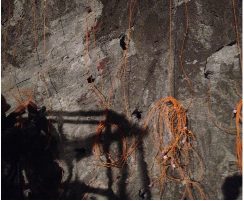
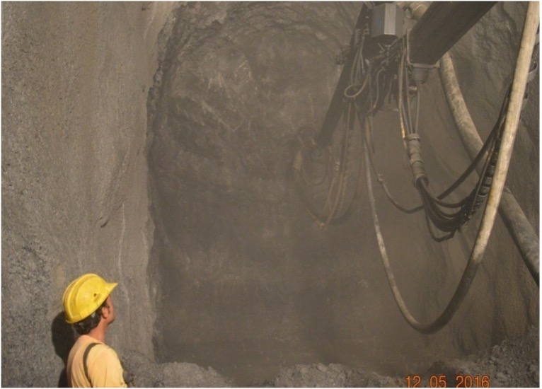
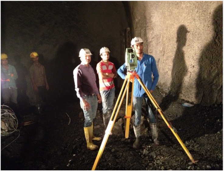
To achieve the designed shape profile marking is required. It has its own significance in the sequential excavation method. Its main purpose is to define the minimum excavation line on the working face. Accuracy in profile marking helps to maintain the minimum excavation line and prevents over breaks. Points are defined and marked by the survey team. Equipment used here is Leica total station with TMS (Tunnel Measurement System) software.

2.1 SURVEY AND PROFILE MARKING

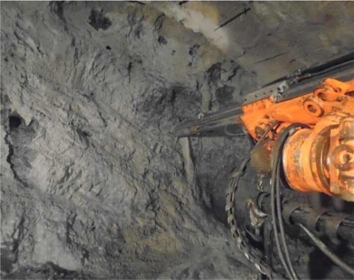
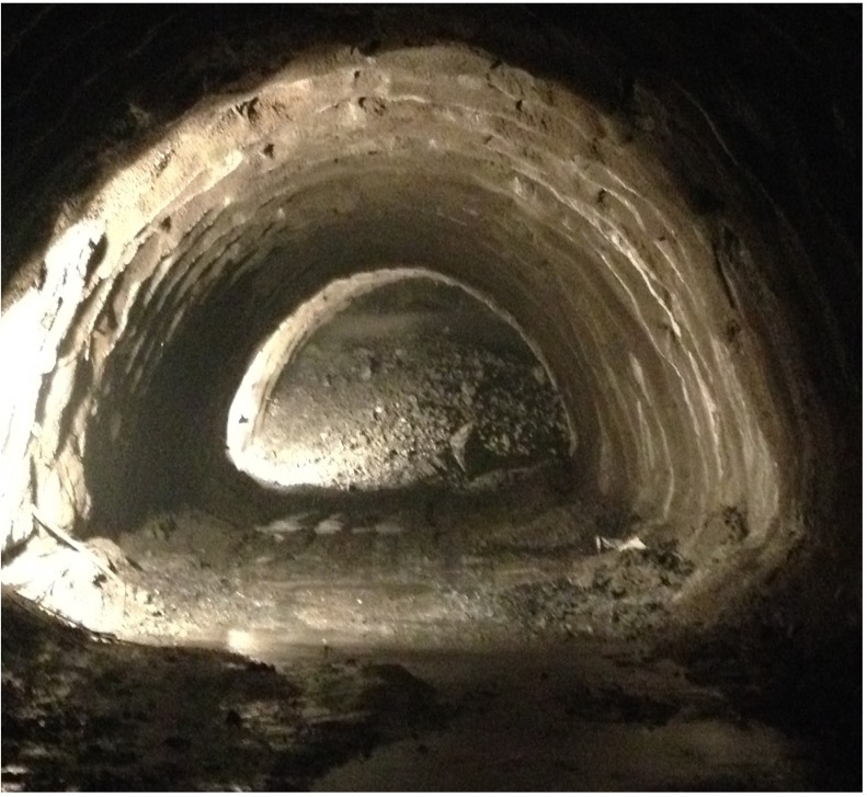
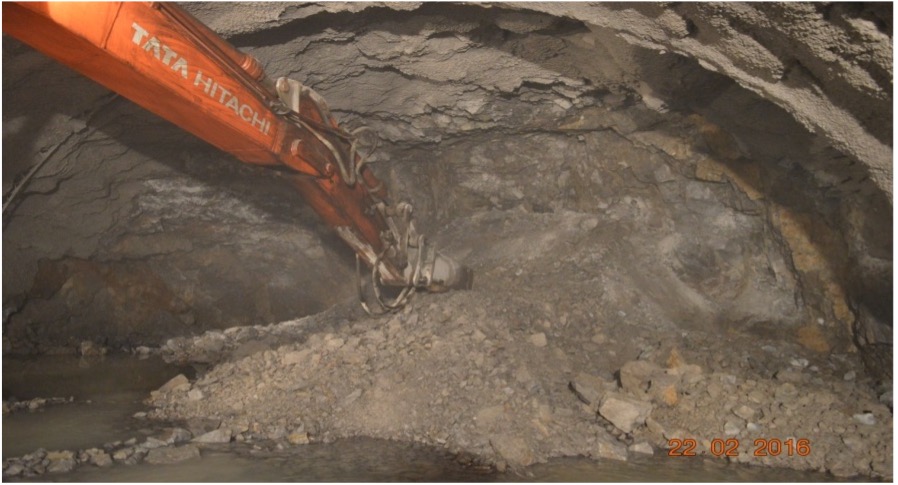
Long tunnels pass through complex geological conditions. Geological predictions in deep tunnels are hard to make merely on the basis of surface observations. If the site conditions require (when the geology is not homogeneous or when there are drastic changes in the strata of the mountain range as the case in sub Himalayan ranges, which is just forming) probe holes up to a length of 20 meters can be drilled on the face of the tunnel along the tunnel alignment to assess the geotechnical information before tunneling regarding the size of the bore, closeness of the drill holes etc. for obtaining optimum tunneling efficiency.

2.3 FACE DRILLING

Once the profile is marked working face is drilled with the help of 2 boom hydraulic boom Jumbo or Tunnel drilling can be performed with Jack hammers, crawler drills and with tunnel boring machines as the case may be depending upon the strata met with. In the sub Himalayan region, the tunnel boring machines will not work since the mountain ranges are just forming and filled with heterogeneous loose strata. So, the tunneling is mostly done with jack hammers or boomers depending upon the strata. The drilling pattern followed is VEG CUT. 107 numbers of holes (variable) are drilled having a diameter of 41mm. The Number as well as length of holes (pull length) varies, depending on the rock type, if the rock encountered is in good condition, then length of the hole can be increased. Generally, 1m, 1.5m, 2m pull lengths are used here, depending upon the Rock class. The number of holes to be drilled, depends upon the observation of the strata based on the probe hole result. Past expiring shows the drilling of around 2 ½ meters long holes will be optimum to obtain a fetch of around 2 meters.

4. LOADING, CHARGING WITH EXPLOSIVES AND BLASTING

Mechanical engineers produce specifications for design, develop, manufacture and install new or modified mechanical components or systems. Mechanical engineers need to be technically minded, able to demonstrate numerical and scientific ability and have problem-solving skills. Mechanical Engineers are responsible for designing, building, installing and maintaining all kinds of mechanical machinery, tool and components. The role sometimes involves preparing heating, ventilation and air conditioning equipment schedules and designing and drawing system schematics.

5. DEFUMING

After the blast, the vicinity is filled with poisonous gases caused by the burning of the explosive (like Ammonium Nitrate, Tri-Nitro toluene etc.) which will not move out in view of non flow of air in the tunnel. Generally, due to their lighter weight they travel along the crown portion of the tunnel. A proper ventilation system with jet fans has been planned to maintain fresh air and to take out harmful gases from the tunnel. Ventilation duct is installed along the crown portion considering the height over less diameter of tunnels. All the workers are provided with air filter masks as a safety precaution. So fresh air is pump through the ventilating duct for at least 30 minutes to replace the stale air with fresh air so as to enable the manpower to do the remaining operations without any fear on the health condition.

5. DEFUMING

Material obtained from blasting/Fragmented rock after blasting is termed as Muck the whole procedure of gathering and removal of muck is known as mucking. Machinery used for mucking depends on the availability of working area inside the tunnels. This is the operation done with an excavator and tippers wherein the blasted tunnel surface splinters are gauged and dumped into the dumping yard. Very sevre checking is to be performed by the Blaster before taking up mucking operation since the explosive in some of the drill holes may not explode and may likely go off while doing the operations of the next cycle.

5. DEFUMING

Once mucking is completed the whole blasted area is thoroughly checked for presence of undercuts or some loose material or cracks which are removed with the use of excavators or breakers. Scaling is necessary to provide accurate excavated profile for the installation of Lattice girders and safety of the workers executing the works. This is an operation done with steel poles and breaker unit to carefully separate the blasted muck with the unblasted surface of the tunnel.

8. 3D Geological Face Mapping

Examining the types and number of joints and type of rock conditions of the obtained face is termed as geological mapping. After scaling and chipping geologist along with survey team and other supporting workers inspect the face. Geologist examines the face and prepares a face log after every pull and keeps a record of the same. Base on the actual site conditions and face log geologist decided whether designed support is enough or less or more for that section. Whereas Survey team examines if any over break is there or not and brings in the notice of the face in charge after which require measures are taken to control the over breaks.

9. SEALING SHOTCRETE

A protecting layer is applied on the obtained face and the periphery to avoid falling of loose materials which is termed as face sealing shotcrete. Minimum 30mm and maximum 50mm face sealing is applied depending on the site conditions. The main purpose of applying face sealing shotcrete is to prevent any casualty which may happen due to falling of loose material from the excavated face. It acts as a protecting layer or umbrella under which workers and machines can perform safely.

10. ERECTION OF RIBS/LATTICE GIRDER

Steel Ribs (ISHB 15 X 150) / Lattice Girder are bent into their required shape and erected exactly at the same level and alignment as per the co-ordinates supplied by the engineer in-charge. Once the protecting layer is applied then survey team along with the supporting staff reaches the face. Survey team with the help of total station marks the location of the Lattice girders and executes the placing of LGs. Lattice girders act as initial support and provides a defined shape to the tunnel.

11. DRILLING AND INSTALLATION OF FOREPOLE & GROUTING

In case of weak rock in the crown portion forepoles are provided for additional support. In this project the length used is 4m with 0.3m center to center spacing for a pull length of 1m at an angle of 50- 7°.These are mainly to assess the strength of overburden above the tunnel wherein holes are drilled radially to the roof of the tunnel in the heading portion. These can help prediction of the cavities, loose pockets; water reservoirs etc above the tunnel and prevent accidents and collapse of the tunnel when precautions are taken to strengthen the tunnel overburden. Based on the observation of the forepoling operations, strengthening operations can be taken up like rock bolting, shotcreting etc. when we predict the roof of the tunnel is formed with loose strata before actually taking up drilling operations.

12. SPRAYING OF SHOTCRETE

Shotcreting is considered as one of the main component of initial support system. Shotcreting is of two types: sealing shotcrete and main shotcrete. Sealing shotcrete is used to avoid loose ground and prevent fall-downs, whereas main shotcrete is used to carry load uintroduced by ground in the lining. After the installation of LGs a thick layer of shotcrete is applied. Putzmister is used to spray the shotcrete. Highly skilled staff is required for this work. Mix inclusive of cement, sand, aggregate and admixture is poured in the putzmister where accelerator is also added and then sprayed for quick setting. Face is cleaned with high pressure air or water before application. A minimum of 1.5 m and maximum of 2.5 m distance between the nozzle and the face should be kept for best results. Thickness of shotcrete layer depends on the rock conditions. If poor rock is encountered, then 300 mm thickness is applied and in case of good rock class thickness is reduced to 250mm to 200mm to 100mm. Two types of reinforcements are used here during Shotcreting: 1) Wire mesh 150*150*60dia, 2) Steel Fiber-2DIf the thickness of shotcrete layer is 250 mm then two layers of wire mesh is applied. One on protecting layer of thickness and other at 130mm. In case of steel fiber 30 kg per cubic meter is used applied directly on the face.

13. ROCK BOLTING

After the application of shotcrete rock bolts are installed to stitch the whole shotcrete with the rock so compact that shotcrete and rock becomes one unit for supporting the whole burden. The rock bolts help to stitch the joints and make it a bulk body, bolts used here are Self-drilling Anchors with a diameter of 32mm and length 3m & 4m in general. 2 boom hydraulic jumbo is again used to drill these bolts in the periphery. A staggered pattern is adopted in installing these bolts with a spacing of minimum 1 m longitudinal and 1.75 radial. Then grout is injected in rock bolts which fill all the cracks up to 3m or 4m. Grout is a mixture of cement and water. Desired quantity of water is added in grout mixture so that it can easily flow in the cracks. Bearing plates of 250*250*10 with nuts are installed after grouting. 10 hours after injecting grout torqueing is done to tighten the bearing plates and if any space is left between plate and the face then padding is done with cement sand mixture in the ratio of 1:4.

Various rock bolts of grouting and non-grouting categories are shown as follows:

  • SN Bolts – Self-drilling Bolt
  • Expansion Rock Bolts
  • Swellex Rock Bolt

13. ROCK BOLTING

NATM is based on the observational approach whole outcome depends on the Geological interpretation and 3D Monitoring data. This method provides flexibility to change the support systems at regular intervals depending on received data from face logs and 3D monitoring. A quick analysis is done and applied on the field saving time, money and material. With this approach and sequence followed better progress is achieved in a safer environment. Deformation data provided by 3D Monitoring ease outs in identifying the exact locations to be countered for additional supports thus reducing the number of mis happenings. Moreover, we can say that NATM provides better options to choose between anticipated conditions and actual conditions due to its flexible nature thus saves our time, money and material and provides better progress in such unexpected conditions.